1. Introduction
Integrating solar PV and battery storage into a microgrid is no longer just an engineering experiment—it’s a mainstream strategy for achieving:
- Higher energy resilience
- Lower operating costs
- Significant emissions reductions
From industrial campuses and data centers to rural communities and island grids, solar‑plus‑storage microgrids are becoming the default architecture for modern distributed energy systems.
This guide explains, step by step:
- How to plan, design, and integrate solar and storage into a microgrid
- Key technical and economic considerations
- Typical architectures and control strategies
- Practical checklists and comparison tables
Written for an international audience of:
- Engineers and project developers
- Facility and energy managers
- Policy and procurement teams
- Investors and technology vendors
2. Understanding Solar‑Plus‑Storage Microgrids
2.1 What Is a Solar‑Plus‑Storage Microgrid?
A solar‑plus‑storage microgrid is a local energy system that:
- Includes solar PV generation
- Includes battery energy storage
- Can operate connected to or independent of the main grid
- Uses a microgrid controller/EMS to coordinate all assets and loads
Typical components:
- Solar PV array(s)
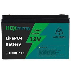
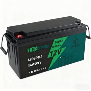
- Battery storage system (often lithium‑ion)
- Inverters (grid‑following or grid‑forming)
- Diesel or gas generators (optional backup)
- Loads (critical, non‑critical, and flexible)
- Switchgear, protection devices, and metering
- Microgrid controller / EMS (Energy Management System)
2.2 Why Combine Solar and Storage?
Integrating storage with solar in a microgrid offers several advantages:
- Smooth solar variability (cloud cover, ramp rates)
- Shift solar energy from midday to evening peaks
- Provide frequency and voltage support in islanded mode
- Enable black start capability for microgrid and critical loads
- Reduce diesel runtime and fuel consumption when gensets are present
3. Overview of the Integration Process: From Concept to Commissioning
Before detailing each step, here’s the high‑level roadmap:
- Define objectives and scope
- Characterize loads and site conditions
- Assess solar resource and site potential
- Size solar and storage
- Select architecture and topology
- Choose technologies and components
- Design control strategy and operating modes
- Plan interconnection and protection schemes
- Develop financial model and business case
- Procure, build, and commission
- Operate, monitor, and optimize
The sections below walk through each step in detail.
4. Step 1 – Define Objectives and Scope
4.1 Clarify the Primary Objectives
Typical objectives include:
- Resilience: Maintain power during grid outages
- Cost reduction: Lower energy costs, demand charges, or diesel consumption
- Decarbonization: Reduce CO₂ emissions and support net‑zero targets
- Grid services: Provide ancillary services (where markets and rules allow)
Be explicit about priorities, for example:
- “Resilience first, then cost optimization”
- “Cost and emissions reduction, with limited resilience requirements”
4.2 Define System Boundaries
Decide:
- Which loads will be within the microgrid (entire facility vs. critical subset)
- Whether the microgrid is intended to be:
- Grid‑connected only, with limited islanding capability
- Fully islandable with long‑duration backup
- Completely off‑grid
Scope decisions influence:
- Solar and storage sizing
- Control strategy complexity
- Capex and Opex expectations
5. Step 2 – Characterize Loads and Site Conditions
5.1 Load Profiling
Obtain at least 12 months of data where possible:
- Hourly or 15‑minute load profiles
- Peak demand and load duration curves
- Segmentation into:
- Critical loads (must always stay on)
- Non‑critical loads (can be shed)
- Flexible loads (can be shifted or modulated)
If measured data isn’t available, develop detailed load estimates and improve them over time.
5.2 Site Conditions and Constraints
Consider:
- Available roof and ground space for PV
- Shading, orientation, and tilt options
- Structural limitations
- Local climate:
- Ambient temperatures
- Humidity and dust
- Extreme weather risk
5.3 Existing Electrical Infrastructure
Document:
- Main incoming feeders and switchgear
- Existing backup systems (diesel/gas gensets, UPS, etc.)
- Protection schemes (relays, breakers, fuses)
- Existing monitoring and control (SCADA, EMS, BMS)
6. Step 3 – Assess Solar Resource and Site Potential
6.1 Solar Resource Assessment
Use:
- Satellite‑based solar resource datasets (global data providers)
- On‑site measurements if available for large or critical projects
Key parameters:
- Global Horizontal Irradiance (GHI)
- Direct Normal Irradiance (DNI) for certain configurations
- Seasonal variation in solar output
6.2 Estimating PV Production
Consider:
- PV module efficiency
- System losses (inverter, wiring, temperature, soiling)
- Degradation over time (commonly 0.3–0.7% per year for many modern modules)
Outputs:
- Annual and monthly PV generation estimates
- Daily generation profiles by month (for matching to load profiles)
7. Step 4 – Solar and Storage Sizing
7.1 Solar Sizing Approaches
There are several strategies:
- Load‑matching: Size PV to cover a portion of average or peak load
- Roof/land constrained: Maximize PV within available footprint
- Capex/IRR‑driven: Optimize PV size based on financial return
Typical design practices:
- For C&I microgrids: PV might be sized to cover 20–80% of facility peak, depending on roof area and economics
- For off‑grid microgrids: PV sized to meet a large share of energy demand, with storage and backup gensets bridging gaps
7.2 Battery Sizing Approaches
Common metrics:
- Energy capacity (kWh): determines how long storage can supply loads
- Power capacity (kW): determines how quickly storage can charge/discharge
Use cases determine sizing:
- Resilience: Enough kWh to support critical loads for desired outage duration
- Peak shaving: Adequate kW to reduce peak demand, and enough kWh for target duration
- Solar shifting: Enough kWh to store surplus PV and release during evening peaks
7.3 Balancing Solar and Storage
Balancing strategies:
- Oversized PV with modest storage for cost‑optimized decarbonization
- Moderate PV with larger storage for resilience and demand management
- Hybrid approach combining both goals
8. Step 5 – Choose Microgrid Architecture and Topology
8.1 AC‑Coupled vs DC‑Coupled vs Hybrid
- AC‑coupled:
- PV and storage each have their own inverters tied to an AC bus
- Good flexibility and retrofitting capability
- DC‑coupled:
- PV and storage share a DC bus with a single DC‑AC inverter
- Potential efficiency gains and better PV clipping recapture
- Hybrid:
- Combination of AC and DC couplings, often in complex or multi‑stage systems
8.2 Grid‑Connected vs Off‑Grid vs Hybrid Microgrids
- Grid‑connected with islanding capability:
- Normal operation connected to utility grid
- Island mode during outages
- Off‑grid:
- No grid connection; microgrid must fully meet demand
- Hybrid:
- Weak or intermittent grid, microgrid supports local stability
9. Step 6 – Select Technologies and Components
9.1 Solar PV Modules and Inverters
Decisions include:
- Module type:
- Mono PERC, TOPCon, or other high‑efficiency modules
- Inverter type:
- Central vs string inverters
- Grid‑forming vs grid‑following (for islanded control)
9.2 Battery Technology
Most common today:
- Lithium‑ion batteries, especially LFP chemistry for stationary storage
Factors to consider:
- Safety (thermal management, fire suppression)
- Cycle life and warranty terms
- Temperature performance
- C‑rate capabilities (charge/discharge rates)
9.3 Microgrid Controllers and EMS
Key capabilities:
- Mode detection and switching (grid‑connected/islanded)
- Load prioritization and shedding
- Forecast‑based scheduling (solar, load, prices)
- Integration with:
- Generators
- EV charging
- Building management systems

10. Step 7 – Design Control Strategy and Operating Modes
10.1 Operating Modes
Typical modes:
- Grid‑connected mode
- Microgrid imports/exports power as needed
- Solar and storage optimize costs and emissions
- Island mode
- Microgrid operates autonomously
- Storage and generators maintain stability and supply critical loads
- Transition modes
- Seamless transfer between modes (fast, safe switching)
10.2 Control Hierarchy
- Primary control:
- Stable voltage and frequency in islanded mode
- Often implemented in inverters and generator controllers
- Secondary control:
- Load‑sharing, voltage/frequency corrections
- Tertiary control:
- Economic dispatch and optimization over hours/days
10.3 Control Objectives
- Minimize cost
- Maximize renewable share
- Ensure resilience and reliability
- Respect technical limits (battery state‑of‑charge, generator minimum loads, etc.)
11. Step 8 – Interconnection, Protection, and Safety
11.1 Interconnection Requirements
Coordinate with the utility:
- Applicable interconnection standards (IEEE, IEC, local codes)
- Anti‑islanding requirements
- Protection coordination with utility relays
11.2 Protection Schemes
Key elements:
- Overcurrent protection (breakers, fuses)
- Over/under voltage and frequency protection
- Islanding detection and controlled islanding/anti‑islanding
- Grounding and earthing practices
11.3 Safety and Compliance
Ensure compliance with:
- Electrical codes (e.g., IEC standards, local equivalents)
- Fire codes and safety regulations
- Battery safety guidelines and manufacturer recommendations
12. Step 9 – Financial Modeling and Business Case
12.1 Capex and Opex Components
Capex includes:
- PV modules and balance of system
- Battery storage hardware and enclosures
- Inverters, switchgear, protection
- Civil works and installation
- Microgrid controller and communication infrastructure
Opex includes:
- O&M costs (inspections, cleaning, replacements)
- Software licenses and communication fees
- Insurance and site security
- Fuel (if generators are part of the microgrid)
12.2 Key Economic Metrics
Common financial metrics:
- Levelized Cost of Energy (LCOE)
- Net Present Value (NPV)
- Internal Rate of Return (IRR)
- Payback period
12.3 Value Streams
For grid‑connected microgrids:
- Demand charge reduction
- Time‑of‑use arbitrage
- Backup power value (avoided downtime costs)
- Ancillary services (where allowed)
For off‑grid microgrids:
- Diesel fuel savings
- Reduced logistics costs
- Improved service reliability
13. Step 10 – Procurement, Construction, and Commissioning
13.1 Procurement Strategy
Options:
- EPC (Engineering, Procurement, Construction) contracts
- Design‑build approaches
- Build‑own‑operate models by third‑party developers
13.2 Construction and Installation
Key tasks:
- Site preparation and foundations
- PV mounting (rooftop, ground‑mount, carports)
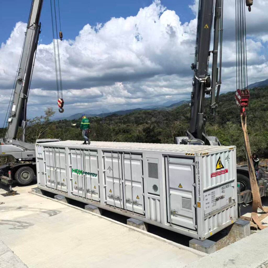
- Battery room or container installation
- Cable routing and terminations
- Control and communication wiring
13.3 Testing and Commissioning
Include:
- Pre‑commissioning checks (insulation, polarity, continuity)
- Functional tests of inverters and storage
- Microgrid controller logic testing
- Islanding and reclosure tests
- Performance verification against design criteria
14. Step 11 – Operation, Monitoring, and Optimization
14.1 Monitoring and Analytics
Use:
- SCADA or EMS dashboards
- Real‑time performance indicators
- Historical trend analysis for:
- Solar yield
- Battery cycling and state‑of‑health
- Load behavior
14.2 O&M Strategy
Plan for:
- PV cleaning schedules
- Inverter and battery maintenance
- Firmware and software updates
- Periodic protection testing
14.3 Continuous Improvement
- Adjust control strategies and tariffs (if applicable) based on observed data
- Fine‑tune battery dispatch to extend life and improve economics
- Plan future expansions (more PV, more storage, load integration)
15. Comparative Table: Integration Steps and Key Outputs
Table 1 – Summary of Integration Steps and Deliverables
| Step # | Step Name | Key Deliverables/Outputs |
|---|---|---|
| 1 | Define objectives and scope | Objectives, load boundaries, resilience targets |
| 2 | Characterize loads and site | Load profiles, critical load lists, site constraints |
| 3 | Assess solar resource | Solar resource data, PV potential estimates |
| 4 | Size solar and storage | PV capacity (kWp), storage capacity (kW/kWh) |
| 5 | Choose architecture and topology | AC/DC/hybrid layout, grid‑connected/off‑grid decision |
| 6 | Select technologies and components | PV modules, inverters, batteries, controller selection |
| 7 | Design control strategy | Operating modes, control hierarchy, optimization logic |
| 8 | Interconnection and protection | Single line diagrams, protection schemes, interconnection plan |
| 9 | Financial modeling | LCOE, NPV, IRR, payback period, value streams |
| 10 | Procurement and construction | EPC contracts, construction schedule, QA/QC plan |
| 11 | Operation and optimization | O&M plan, monitoring system, continuous improvement loop |
16. Typical Solar‑Plus‑Storage Microgrid Configurations
Table 2 – Common Configurations by Use Case
| Use Case | Architecture | PV Size (Relative to Load) | Storage Role |
|---|---|---|---|
| C&I campus | Grid‑connected AC‑coupled | 20–80% of facility peak | Peak shaving, backup, solar shifting |
| Data center | Grid‑connected with UPS | Often limited by roof space | Backup, power quality, limited shifting |
| Island microgrid | AC or hybrid AC/DC | Often sized for high solar share | Bulk energy, firming, island operation |
| Rural off‑grid | AC‑coupled | Covers majority of daily energy | Night supply, resilience, diesel reduction |
| Industrial site | Hybrid with gensets | 30–60% of energy | Cost optimization, resilience |
Values are indicative and vary with specific project requirements and constraints.
17. Technical Comparison: AC vs DC Coupling for Solar and Storage
Table 3 – AC‑Coupled vs DC‑Coupled Integration
| Feature/Aspect | AC‑Coupled | DC‑Coupled |
|---|---|---|
| Retrofitting existing PV | Easier; storage added via AC link | More challenging; may require major reconfig |
| Efficiency | Slightly lower due to multiple conversions | Potentially higher (fewer conversions) |
| Control flexibility | High; separate control for PV and storage | Tight integration; can recapture clipped energy |
| Complexity | Moderate; well‑known architectures | Higher; needs careful design and controls |
| Cost | Competitive; more components | Can be lower or higher depending on design |
| Use cases | Retrofits, flexible C&I microgrids | New builds, high PV penetration, utility‑scale |
18. Risk Management and Best Practices
18.1 Technical Risks
- Poorly designed protection leading to nuisance trips
- Inadequate thermal management for batteries
- Insufficient control logic for complex operating modes
Best practice: Use experienced engineering teams, validated reference designs, and thorough testing.
18.2 Financial and Regulatory Risks
- Tariff structures changing post‑investment
- Uncertain rules for exporting power or participating in grid services
- Currency risk in markets with volatile exchange rates
Best practice: Build conservative assumptions, secure long‑term contracts where possible, and align with regulatory guidance.
18.3 Operational Risks
- Insufficient local O&M capabilities
- Component failures without redundancy
- Cybersecurity vulnerabilities in connected systems
Best practice: Invest in training, spare parts, cybersecurity practices, and remote monitoring.
19. SEO‑Friendly Conclusion
Integrating solar and storage into microgrid systems is a structured process that combines:
- Clear objectives and scope
- Detailed load and resource assessment
- Careful sizing of PV and storage
- The right architecture and technology choices
- Robust controls, protection, and financial planning
When executed properly, solar‑plus‑storage microgrids can:
- Dramatically improve resilience for critical loads
- Deliver lower and more predictable energy costs
- Substantially reduce greenhouse gas emissions
- Provide a flexible platform for future electrification and digitalization
Whether you’re planning a C&I campus microgrid, upgrading a data center, or designing an off‑grid system for a remote community, following these steps will help ensure a technically robust and economically sound integration of solar and storage.
20. Professional Q&A: Integrating Solar and Storage in Microgrid Systems
Q1: How do I decide how much solar vs how much storage to install?
Answer:
Start from your objectives and load profile:
- For cost optimization in a grid‑connected facility:
- Size PV to maximize self‑consumption and financial returns (often limited by roof space).
- Size storage for peak shaving (kW) and time‑of‑use shifting (kWh) based on tariff structure.
- For resilience:
- Size storage to support critical loads for the required outage duration (e.g., 4–12 hours or more).
- Ensure PV is sufficient to recharge batteries between outages or during prolonged events.
Use iterative simulations (e.g., hourly modeling) to test different combinations and optimize based on NPV or IRR.
Q2: Can a solar‑plus‑storage microgrid operate without any diesel or gas generators?
Answer:
Yes, in some cases, particularly where:
- Loads are relatively predictable and modest
- Solar resource is strong and consistent
- Storage is sized generously
However, for many critical facilities and high‑reliability applications, having a small dispatchable backup source (e.g., diesel, gas, or fuel cell) is still common to:
- Cover extended low‑sun periods
- Deal with unexpected demand spikes
- Provide redundancy and extra resilience
A renewable‑only microgrid is technically feasible but must be carefully designed to avoid unacceptable loss of load probability.
Q3: What is the difference between grid‑following and grid‑forming inverters in a microgrid?
Answer:
- Grid‑following inverters:
- Rely on an external voltage and frequency reference (typically the main grid or a synchronous generator).
- Common in standard solar installations; they “follow” the grid.
- Grid‑forming inverters:
- Act as a voltage and frequency source, enabling islanded operation without a spinning generator.
- Essential for fully renewable microgrids and advanced microgrid architectures.
In modern microgrids, especially those aiming for high renewable share, grid‑forming inverters play a crucial role in maintaining stability when operating in island mode.
Q4: How important is the microgrid controller compared to the hardware (PV and batteries)?
Answer:
The microgrid controller (EMS) is critical:
- It determines when and how solar, storage, and generators operate.
- It handles mode transitions (grid‑connected to islanded and back).
- It enforces priorities (cost vs resilience vs emissions).
A well‑designed controller can:
- Extend battery life by avoiding unnecessary cycling
- Improve economic performance by optimal dispatch
- Prevent instability and miscoordination among multiple devices
Hardware quality is crucial, but without a robust control layer, the system will not perform as intended.
Q5: What are the most common mistakes in integrating solar and storage into microgrids?
Answer:
Common mistakes include:
- Underestimating load variability and future growth, leading to undersized systems.
- Ignoring protection coordination, causing nuisance trips or unsafe conditions.
- Overfocusing on capex and neglecting O&M and lifecycle costs.
- Poor integration between HVAC, building management systems, and microgrid controls, missing demand flexibility opportunities.
- Insufficient testing of islanding and resynchronization procedures.
Mitigation: use experienced designers, perform comprehensive studies, and run realistic tests before full commissioning.
Q6: How do regulatory and market conditions influence microgrid design?
Answer:
Regulation and market rules dictate:
- Whether you can export energy and at what price
- How demand charges and TOU tariffs are structured
- If and how microgrids can provide ancillary services to the grid
- Interconnection requirements and compliance costs
In some regions, generous net metering or export tariffs encourage larger PV systems; in others, limited export options push designs toward maximizing self‑consumption and storage use. Always align your microgrid design with current and anticipated regulatory frameworks.